 Click Here for Site Directory
TAKING A LOOK AT WINCHES
By Dave WINTLE
Copyright David Wintle January 2006
David Wintle has been kind enough to allow us to print his interesting article on balloon winches. He does ask for help though with some unanswered questions on winch usage. If you can help please let him know.
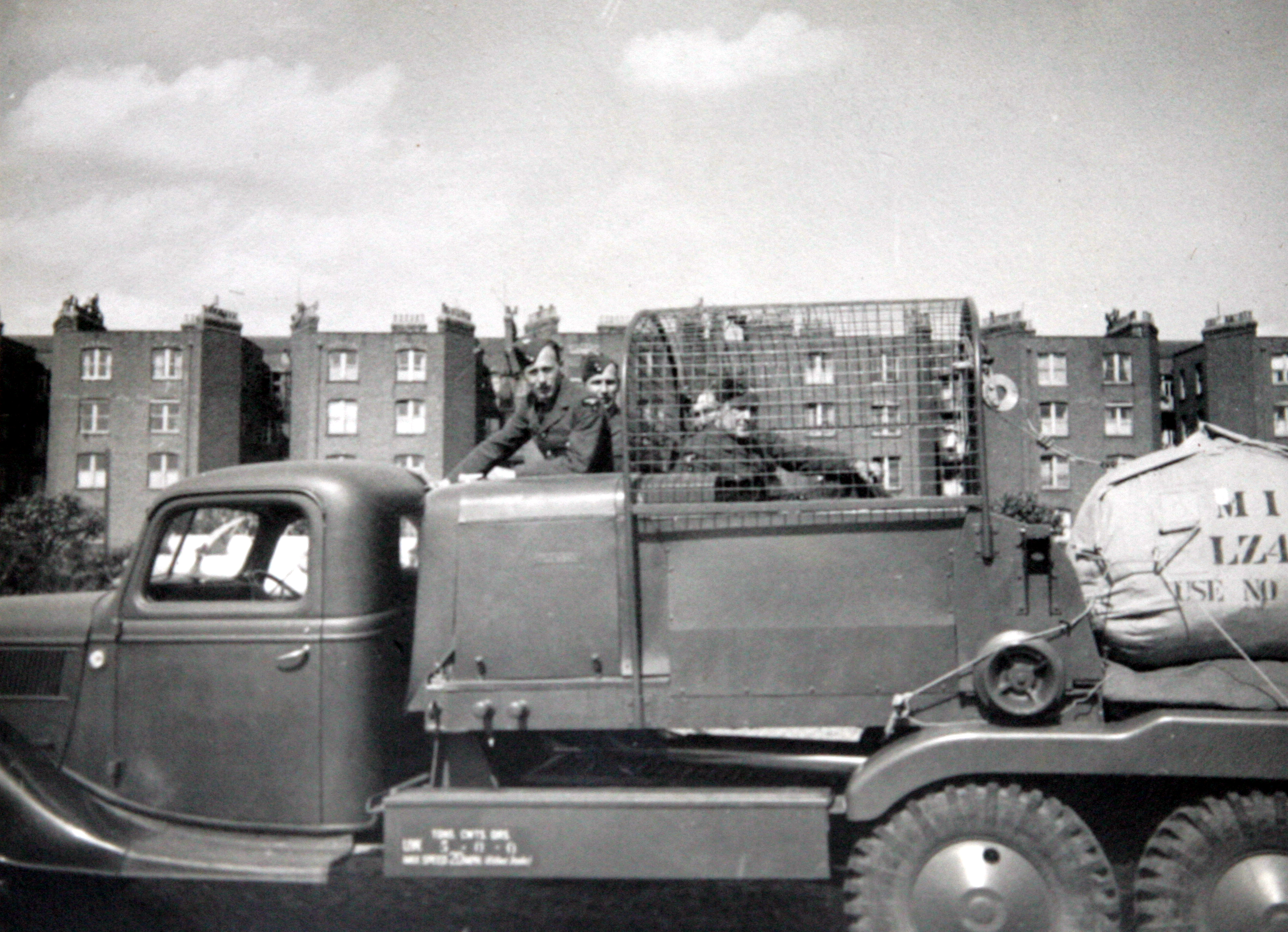
This is a picture of a typical winch vehicle and although not all of it is visible it illustrates the style of it very well.

Note the packed balloon on the back and Beresford in the protective cage
Before I start this article I would just like to point out that although I am ex-RAF I am not a trained balloon operator and it is based on my memories of visiting quite a number of balloon sites as a school-boy teenager during the war, from photographs I have seen over the years and more recently from a close look at the winches at the RAF Museum at Hendon and the Imperial War Museum at Duxford. I have also obtained pictures, diagrams and copies of winch mechanisms taken from Winch Manuals from the RAF Museum at Hendon and also Duxford who have both
been most helpful and co-operative. However, my knowledge of winches is still far from complete.
I am sure quite a number of readers will have seen the winches at Hendon and Duxford and to the casual observer apart from their different paint schemes look very similar but are both of different types. The one at Hendon is the one used in greatest numbers and is the Fordson ‘Sussex’ Type E917T, the E being for English, the 9 denotes the year of manufacture - 1939, the 1 - 221 cubic inch engine, 7 - 157 inch wheelbase and the T for truck, and is painted in peacetime Air Force Blue. The Duxford winch is a Fordson Type WOT 1 ( War Office Type 1) and is painted in wartime camouflage khaki. The Fordson Sussex Chassis is of pre-war American design based on the then popular ‘streamline’ concept with curved surfaces and large bulbous headlights, rounded radiator grill and bumper bar. The WOT 1 Type winch is a war-time made chassis with a much more ‘utility’ appearance with a squarish shaped radiator with a bumper bar across its front. The cab is also of a squarer shape with two windows at the rear while the ‘Sussex’ has one window in the centre. The WOT 1 also has mudguards over the rear wheels while those of the ‘Sussex’ are uncovered. However, winch designs can vary and I have seen photographs of Sussex winches with mudguards. Some winches were also mounted on Austin made chassis.
Neither the Hendon or the Duxford winches are of truly authentic construction and both have been rebuilt with some parts from other vehicles. The original search for a winch was started by Ken Kelly in the 1960’s who lives in America. Like myself, he had happy war-time memories of barrage balloons and decided to find out if there were any artefacts of Balloon Command still preserved in this Country. As there was nothing of any real significance he decided to start a search for a winch lorry but without success. It was not until 1989 that he read in a magazine that a winch chassis had been found by a Mr. Eddie Smith rotting on a farm in Suffolk. He contacted Eddie and they decided to purchase and restore it. Ken undertook to finance the project and Eddie the restoration work. With a friend, Ted Bird they dug it out and the farmer transported it to another farm in Essex where the owner allowed Eddie to work on it.
Much of the bodywork had rusted too much to be restored and the driving cab had to be removed and the search started for a replacement. Eventually a similar one was located through an American magazine of the same pattern, American Fordson cabs being of the same design except for being left hand drive. This was purchased and shipped to Britain at no mean cost. Eddie took everything apart, cleaned and repainted everything and altered the cab to right hand drive. The search then began for a winch unit and one was located in the UK which had fortunately been kept in storage by a British vehicle enthusiast and was in good condition. Remaining other parts and items were located and after almost 5 years continuous work the winch was finally finished with other helpers including Eddie’s son Richard Smith and Ted Birds son Martin, Ted having unfortunately died before the restoration had been completed. There were also many others who gave valuable help in all sorts of other ways.
In June 1994 Eddie was able to take the winch to France for the 50th. Anniversary of the Normandy Landings where it won the cup for the best restored British vehicle from the very many taking part and it also went on to win two other awards later on.
After this Eddie then went on to bring the Duxford winch up to its present appearance, and more representative of a WOT 1 winch, it having previously been restored to some extent but was not of the correct appearance, the chassis being too long. Eddie had to reduce it to the correct length by cutting off some eleven inches and making other modifications including the making of new tool boxes and getting hubs for the rear wheels made.
We have Eddie Smith and Ken Kelly to thank for providing these two wonderful vehicles as memorials to all those who served in World War 2 RAF Balloon Command and to give future generations the chance to see the type of winches that were used and of giving us of the older generation, a reminder of happy times in our youth watching barrage balloons riding the wartime skies.
There is also another type of winch which was extensively used and this is the Four Wheel Trailer Winch. This was mounted on what I believe was an ‘Eagle’ trailer similar to that used for transporting gas cylinders and was equipped with a hand operated brake located on the bottom of the chassis to lock the wheels. Like the other two types of winch already mentioned it carried a Wild winch unit, all of these were made by M. B. Wild & co. of Birmingham. While there may have been slight differences in some of these, they all looked very much the same and this firm continued in business until the 1980’s. In Bristol, where I did all my balloon watching there were three separate barrages, one around the City Centre and the docks, one around the docks at Avonmouth and a third around the Bristol Aeroplane Company and the airfield at Filton all of which came under the administration of No.11 Balloon Centre at Pucklechurch within 32 Group, Balloon Command. There was roughly a 50/50 split between self-propelled ‘Sussex’ winches and the trailer type but I do not know if this was the same for other Balloon Groups. About 1942 for some reason, the trailer winches were lifted off their trailers and mounted on two parallel strips of concrete laid on a concrete plinth and ended up several inches closer to the ground. The purpose for this I have never discovered, whether it was to make them more secure, or so they could be put to other uses, or just to keep them in store. However, when the ‘Flying Bomb’ attacks began in June 1944 the winches were soon re-united with their trailers and deployed over- night to the South East Coast for the defence of London. That brought Bristol’s balloon barrage to a very sudden end.
The winch cage was protected by a strong steel wire mesh as when the balloon was being flown off the back of the winch and was hauled down in windy conditions there could be handling lines flying around with considerable force and so the winch operator needed to be well protected. Due to static electricity building up within the winch, in order to avoid the possibility of a rather nasty shock, the operator was always advised to jump onto the winch and to keep both feet clear of the ground. On entering the winch there was a secondary slatted wooden seat for use by a trainee or an observer situated over part of the cable drum which was located behind the cage and also the 30 Horse Power Ford V8 engine. Next to the secondary seat was the one piece pressed steel seat for the winch operator and to his/her right the Starter Button and the five gear Gearbox similar to that of a car, the reverse gear being used for paying out and the other four gears for hauling in. Bottom gear being the slowest and used when the balloon was near the ground or if there was a heavy load caused by the strength of the wind. Second and third gear were used according to the load on the cable but third gear was used for normal hauling and top gear for exceptional use when for some reason the balloon needed to be hauled in quickly and also for light hauling.
Beyond the Gear Lever was a Control Box with the Ignition Switch, Ammeter, Dash Light Switch and a Spotlight Switch. The spotlight itself was mounted on the top of the cage behind the Operator and was to illuminate the Leading Off Gear so the Operator could see he was not paying out the cable faster than the balloon was rising during darkness.
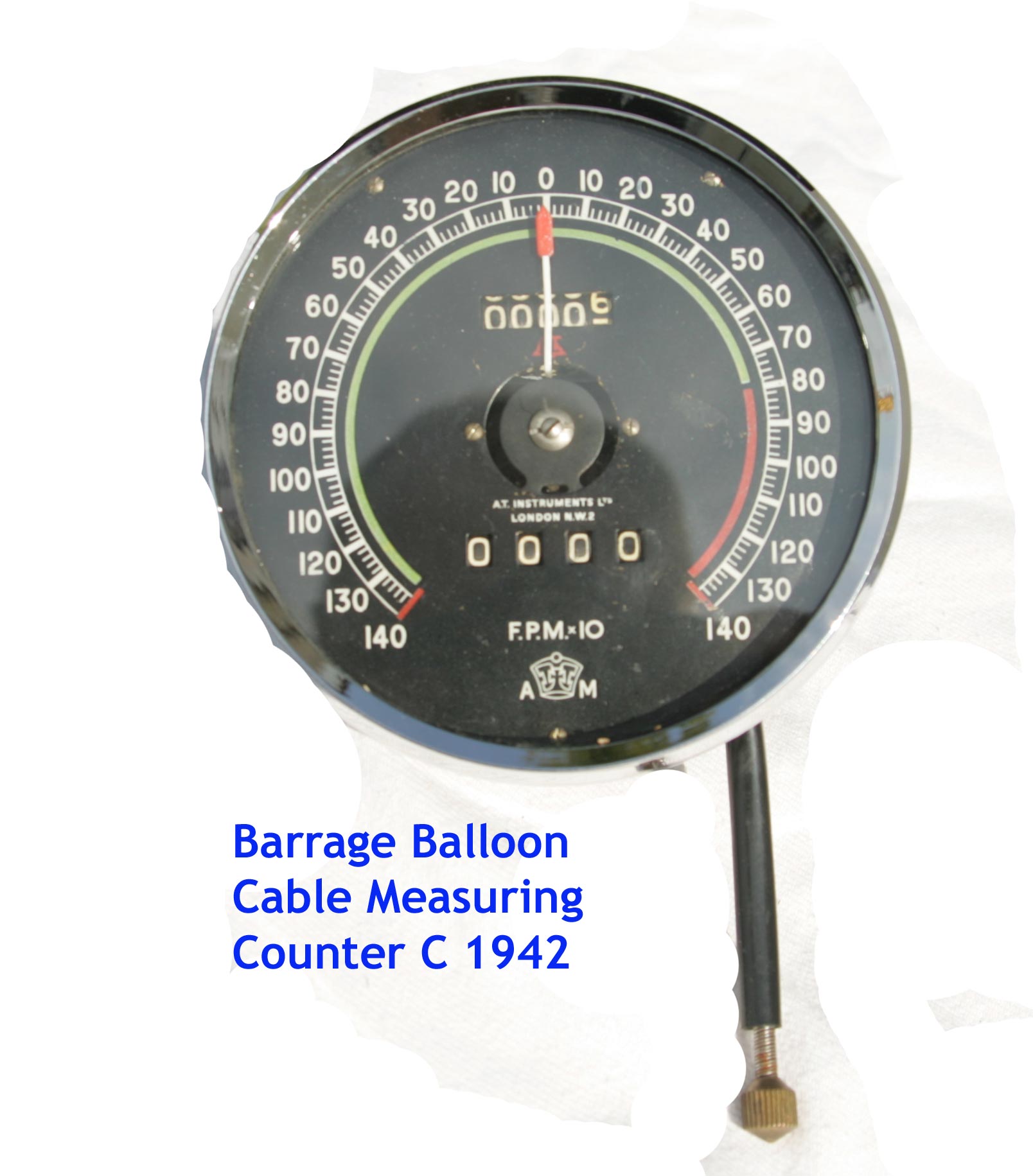
There were three instruments on the Dash Panel in front of the Operator, to the left, the Paid Cable Meter to indicate the speed at which the cable was being paid out, The top of the dial started at 0 and when paying out, went round to the left and to the right when hauling in.

This stopwatch was used by 953 Squadron for timing balloon ascents/descents
In the centre of it was a counter like a mileometer, indicating how much cable had been paid out and read up to 10,00 feet, however, cable drums only normally carried 5,000 feet of cable. To its right was the Cable Tension Meter reading from 0 to 50 Cwt. indicating the actual load or pull on the cable and in between the two was the Fuel and Oil Indicator. There were three foot pedals, the Clutch, the Payout brake used to control the speed of paying out and holding the balloon for short periods, and the accelerator. There were three hand levers, on the left was the Snatch Brake which was a one way action brake which stopped the balloon from rising but did not interfere with hauling down and could also be used as a safety measure when the balloon was brought to rest and then released again when hauling was resumed. The middle lever was also a Paying-out brake which could be used to slow down the balloon with a hand grip at the top to ‘lock’ the cable when the balloon needed to be held at rest for longer periods of time. The third levers’ purpose I am not too sure about but the manual states that the Bollard which was a small winding device on the outside of the cage and used to bring the balloon down to ground level when it had been hauled right down to the winch. Later during the war improvements were made to balloon ‘beds’ with a pulley wheel securely concreted into the ground in the middle of the bed and the balloon cable led out horizontally from the winch, around the pulley wheel and then up to the balloon. When the balloon had been hauled right down to the pulley this was known as the ‘Close Hauled’ position. As there were twelve flying wires from the cable end up to the attachment points on the balloon, it was still some twenty feet up in the air and too high for any work to be carried out. To bring it down to ground level, six of the mooring lines were threaded through pulley blocks which also were concreted into the ground and tied to a wire cable that came out from the Bollard. The Bollard was then operated and the cable wound in, pulling the balloon right down to the ground. Unfortunately I yet have to discover if this third lever was for the Bollard or for some other purpose and if a reader could give me any information on just how the Bollard was operated, I really would be most grateful to them. My address and telephone number is below.
Dave Wintle,
.