 Click Here to Return to
Site Directory
Click Here to Return to
Site Directory
Click Here to Return to
Site Directory
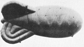
Anyone who trained in a Barrage Balloon Training Unit would have become an expert at knots of all types and also an expert at splicing and general maintenance of ropes and cordage of a large variety of types and designs.
During the training of Balloon Operators they were made to practice and be fully conversant with all types of ropes and cables and in my opinion would have been as capable with knots and splicing as any sailor of the day. These knots all had specific uses and application with barrage balloons.
Typical knots taught were:
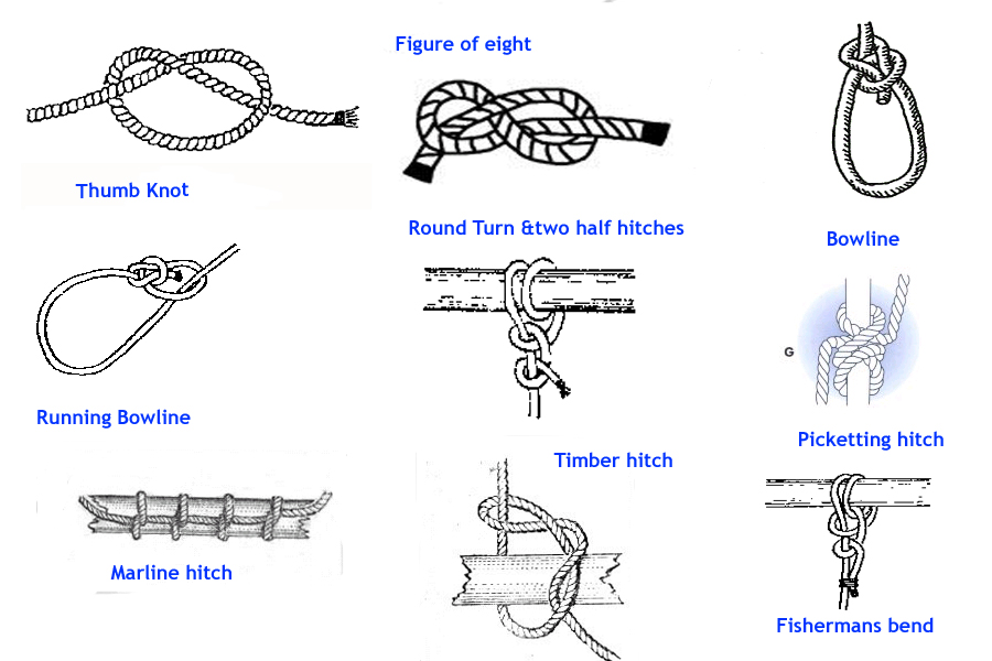
Other knots were:
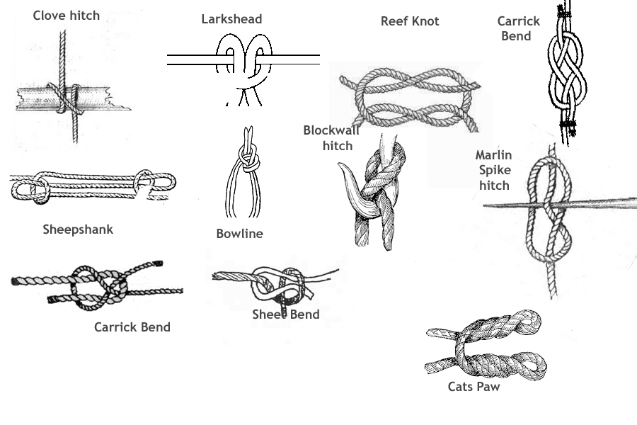
All of these knots had uses in balloon management and maintenance.
The wire used in balloons was flexible steel wire (F.S.W.). The twist or lay in the wire was always right hand laid. To prevent corrosion the wire was drawn to size and coated with hot galvanising or zinc. The wire was tested by the manufacturer for four distinct tests that it had to pass:
1. Tensile testing to see how much it would stretch when a weight or force was applied to it.
2. Torsion testing to see how it responded to a twisting effect or force.
3. Ductility test to see how it responded to being bent without actually breaking.
4.Wrapping test where the end of each hank of wire would have been wrapped closely around its own diameter eight times. Next it was unwound with the exception of the last turn. The wire was expected to show no evidence of any fractures.
On occasions it became necessary to have to join balloon cable, these joints were never popular and the joints had to be as far apart as possible and at least 5 fathoms apart ( 50 feet or approx 15000 mm). The cable came pre-wound onto drums or reels, there were two grades: Extra flexible and Ordinary flexible cable. The Extra flexible could only be wound onto a drum or reel where the drum diameter was less than 40 x the diameter of the cable and the Ordinary flexible cable could only be wound onto a drum or reel where the drum diameter was less than 30 x the diameter of the cable. The wire cable was always greased using natural grease obtained from sheep (lanolin).
The cable had a working load of 1/6th of the known breaking strain, except where the safety of human life was concerned when it was altered to 1/16th of the known breaking strain but NOT less than 1/10th of the known breaking strain.
The Low Zone (LZ) Balloon used a flying cable that was flexible steel wire (FSW) that was known as KB 5. W.6., this meant that it was a 6 stranded wire x19 with a hemp core- in other words there 19 separate strands and each strand was made up of 6 individual wires. This had a breaking strain of 3.25 tons and a diameter of 0.27 inches (approx 6.5 mm). The cable weighed only 100 lbs for every 1000 feet flown. So when a balloon was flown at 5,000 feet the weight of the cable was 500 lbs hanging on the balloon.
There was a cable known as KB1. W6, this was a 7 stranded wire (7x7), in other words there 7 separate strands and each strand was made up of 7 individual wires. with a breaking strain of 1 ton. The diameter was 0.14 inches (approx 3.75 mm). This particular wire rope was fitted to the balloon as winch rigging and strops for handling practice.
The rigging wires were fitted to the balloon in pairs:
Each set had a precise length and this was the same for both port and starboard rigging wires.
No 1 was 8.50 metres
No 2 was 7.78 metres
No 3 was 7.27 metres
No 4 was 7.31 metres
No 5 was 7.90 metres
No 6 was 9.61 metres
These different lengths were necessary due to the fact that the balloon riggings were attached to the balloon at various points along the port and starboard sides. The riggings were attached to a series of patches known as "ton" patches (since they could take 1 ton of weight on them). These patches were attached to the balloon to make a straight line through them in the horizontal plane each side of the balloon. The riggings were then gathered together and meet under the centre of lift of the balloon. Simple inspection shows that the No 1 and No 6 would be the longest as they would form the edge of a triangle, the other four rigging lines being very similar but not exactly the same in length.
(Diagram to be inserted)
There was another cable known as K.B./E.Q./24 W2. This was a seven strand wire (7x14), in other words there 14 separate strands and each strand was made up of 7 individual wires. that was braided on the outside to prevent chaffing. It was used for internal valve lines and pulley strops.
It had a breaking strain of 10 cwt or 1120 lbs, a diameter of 0.18 inches ( approx 3.0 mm). As an internal valve line it was 8.0 (approx 26 feet) metres in length and as a pulley strop it was 2.8 metres (approx 9 feet).
The next cable to be found was known as ripwire. This was a 7 stranded wire (7x7), in other words there 7 separate strands and each strand was made up of 7 individual wires.with a breaking strain of 560 lbs and a diameter of 0.08 inches (approx 2.5 mm). This was 2690mm long (approx 3 metres) and acted like cheese wire. It was threaded through what was known as the rip-panel which was a special panel in the balloon hydrogen envelope that was designed to rip open when the rip wire was pulled and cause emergency deflation of the balloon. Any operator who accidentally pulled the ripwire and deflated the balloon could find themselves in big trouble and yes it did happen!!
In the late 1930 and early 1940's it was apparent that balloons were vulnerable to lightning strikes in a thunderstorm as the metal cable acts like a lightning rod many thousands of feet long. This problem meant that a lightning strike might cause the balloon to burst into flames due to the hydrogen gas and secondly the lightning discharge might injure or kill any personnel or animals close to the cable and winch on the ground. The problem was looked at by the National Physical Laboratory.
The Balloon Command carried out many large scale experiments to see how balloons reacted in thundery weather, they did point out that these experiments would need to be repeated under climatic conditions elsewhere in the world to find out how balloons behaved in other countries.
All balloon crews were taught that immediately on arriving at a balloon site they had to ensure that the metal earth pin was correctly fitted into the ground (up to the standard crosspiece) and was deep enough into the soil. They were told to pour water over the pin to ensure good electrical contact between the earth pin and the soil. The connection between the earth pin wire and the pin itself had to be excellent. The pin had to remain in the earth until all flying operations were completed. If the winch was a mobile one, it might be necessary to move the winch to another part of the site and it was imperative that the earth pin was to be withdrawn but allowed to trail on the ground as the winch was moved elsewhere and the pin refitted immediately the winch was stationary.
If a balloon was flying and a thunderstorm appeared to be beginning the winch operator had to remain in the winch at all times ready to take operating orders from his superior officer. The winch operator was in no danger provided he or she did not try to be in contact with the winch and the ground at the same time. The remainder of a balloon crew were told not to approach within 10 to 15 yards ( 11 meters to 17 metres) from the pin or winch. In thundery weather the balloon operator were all taught to stay on the winch and getting on or off should be avoided at all costs. However if an operator had to get off the winch in thundery conditions they were trained to jump clear of the winch and land on the ground with two feet ensuring they were not in physical contact with the winch in any way.
The National Physical Laboratory began to measure two things:
1) The magnitude of the lightning stroke current in the balloon flying cable when it was struck
2) The small currents present in the cable at regular intervals and especially in the early stages of the storm growth.
In this way they could establish how storms destroyed balloons and whether it was possible to forecast the lightning risk level by measuring the cable currents and compare those readings with the predicted weather forecast.
A lightning current indicator for balloon cables was designed and crews were taught that if a magnetic current indicator was to be fitted or removed or indeed any other fixings needed adjustment on the cable then it was essential to do such a procedure while standing firmly on the winch and having no contact with the ground. They were never to contact the ground and winch simultaneously.
The magnetic indicator was fitted to a holder that was attached to the cable wire a few feet above the winch. The indicator device itself had to be about 4 inches (100 mm) away from the cable. The holder need to be fixed in a horizontal position.